The laboratory analysis of concrete samples is essential to identify the presence of any contaminants or additives and allow the production of durable specifications for concrete repair.
Further analysis or test methods may be used in identifying areas most susceptible to deterioration as well as the confirmation of material strength and composition.
Chloride
The determination of the presence of chlorides in any reinforced concrete structure is crucial to the selection of the correct specification for repair. The presence of chlorides in coastal structures is normally due to water or wind-blown ingress, however many inland concrete structures suffer from the problems caused by chloride attack on reinforcement due to the ingress of de-icing salts, or the inclusion of Calcium Chloride during casting. The current recognised threshold for chloride induced corrosion is 0.35 to 0.40% chlorides by weight of cement. Determination of Chloride from dust samples should be by a UKAS accredited laboratory, in accordance with BS 1881: Part 124: 2015.
HAC
HAC differs from Portland cement, being composed of calcium aluminates rather than calcium silicates. Its rapid strength development made HAC popular for precast concrete in the UK during the 1960s. Mineralogical ‘conversion’ however, sometimes caused catastrophic reductions in concrete strength and increased vulnerability to chemical degradation. Three UK roof collapses in the mid-1970s led to widespread inspection and monitoring of HAC concrete units, exhaustive research and curtailment of HAC use for structural purposes. A large stock of UK buildings containing HAC concrete remains, in which the HAC is now usually highly converted. Whilst the probability of sudden collapse is now perhaps remote, there is continuing concern over long-term durability, particularly where carbonation has occurred to the depth of steel reinforcement. Analysis of samples for HAC should be carried out by a UKAS accredited laboratory in accordance with BRE IS 15/74.
Half-cell Potential Surveys
Steel embedded in good quality concrete is protected by the high alkalinity pore water, which, in the presence of oxygen passivates the steel. The loss of alkalinity due to carbonation of the concrete or the penetration of chloride ions arising from marine or de-icing salts can destroy the passive film. In the presence of moisture and oxygen corrosion of the steel occurs. A characteristic feature of the corrosion of steel within concrete is the formation of macro cells; that is the coexistence of two areas of different electric potential appearing on the same steel surface. This forms a short-circuited galvanic cell, with the corroding area as the anode and the passive area the cathode. The current flow in the concrete is accompanied by an electric field which can be measured at the concrete surface, resulting in equipotential lines that allow the location of the most active corrosion to be identified by the most negative potentials. This is the basis for potential mapping which has become a technique applied to the inspection of reinforced concrete structures and detailed within ASTM C876–09. According to the ASTM method, corrosion can only be identified with 95% certainty at potentials more negative than -350 mV. Experience has shown, however, that passive structures tend to show values more positive than -200 mV and often positive potentials. Potentials more negative than -200 mV may be an indicator of the onset of corrosion.
Core Sampling and Compressive Strength Testing
The removal of core samples for laboratory analysis allows a wide range of definitive data to be obtained, the aggregate type, size, positioning and condition may be crucial to the overall repair recommendations. Similarly, the level of compaction and water cement ratio play an integral part of the overall assessment procedure. In addition, the use of an electron microscope allows the cement paste composition to be analysed in depth, with the effects of carbonation and chloride migration being able to be plotted precisely against reinforcement depth. The effects of heat transfer through cover concrete as a result of fire are clearly identifiable using core samples and laboratory analysis, where site based procedures are less concise. The overall compressive strength of the concrete may also be determined by crushing the sample in accordance with Compressive strength–BS EN 12504-1 and BS EN 12390.
We carried out a concrete condition survey and corrosion assessment of the columns at Smithfield Poultry Market in the City of London. The market’s domed reinforced concrete roof slab, pierced by round window apertures, is carried on V-shaped columns, and our testing concentrated on the column bases below the waterproofing line.
We carried out a visual and hammer tap survey of the column bases and a covermeter survey to measure the depth of cover to the reinforcement. We tested carbonation depth to BS EN 14630 with phenolphthalein indicator, took moisture content readings in drilled holes, and sent concrete dust samples to a UKAS-accredited laboratory for chloride analysis to BS 1881-124.
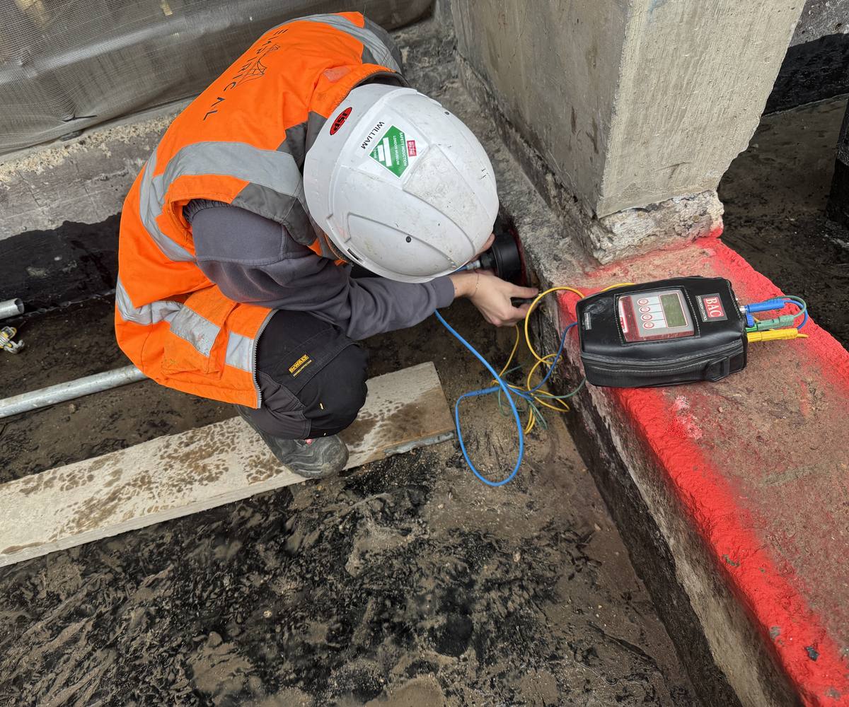
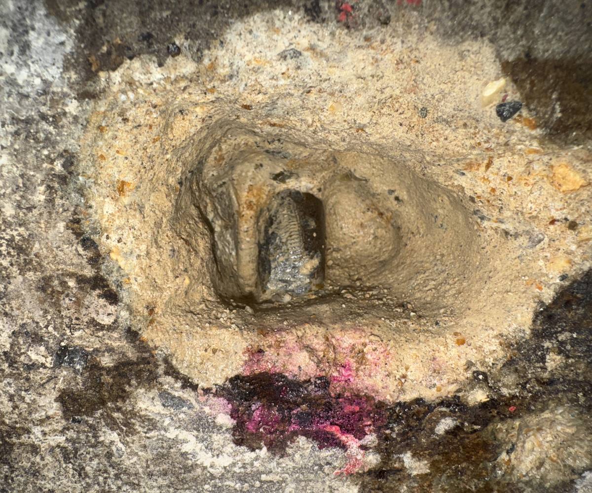
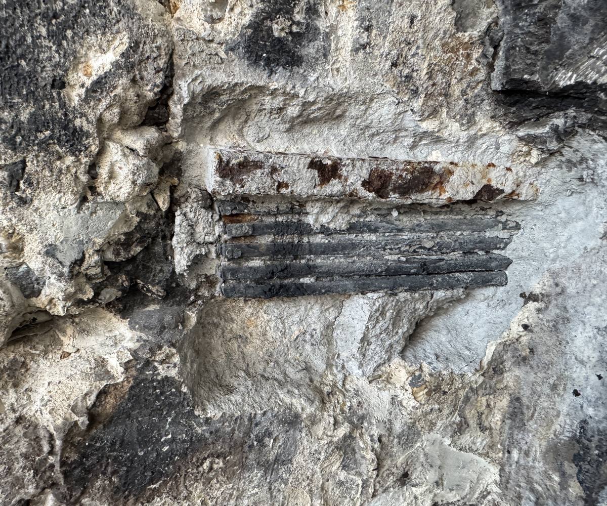
To assess corrosion of the reinforcement we took half-cell potential measurements to ASTM C876. Where the readings indicated a risk of corrosion, we measured concrete resistivity and the corrosion rate by linear polarisation resistance, and at the higher corrosion rates we opened localised breakouts to inspect the steel directly. We also carried out Shore hardness tests on the exposed rubber bearings at the four corner columns. The results were set out in an interpretive report with repair recommendations.
Smithfield Poultry Market
Underside of a wide, curved concrete roof slab pierced by rows of small round openings, above a large open interior with green steel framing and construction work below
Smithfield Poultry Market
Technician in a white hard hat and orange high-visibility vest crouching at the base of a concrete column, holding a probe against it, with leads running to a handheld meter resting on a red-painted kerb
Smithfield Poultry Market
Close-up of a small breakout in a concrete surface exposing a short length of ribbed bar at its base, with fine dust around the hole and bright pink staining on the concrete just below it
Smithfield Poultry Market
Concrete cut back at the base of a column to expose a dark, layered bearing pad, with a rust-stained strip running along its top edge
Design Museum
Location
Kensington, London
Date
July 2025
Description
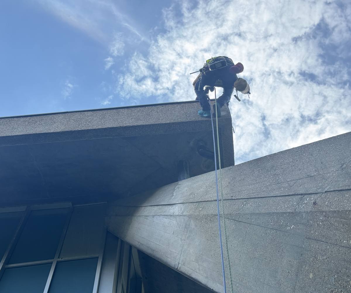
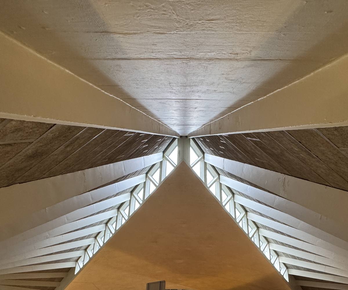
We carried out a concrete condition survey with on-site and laboratory testing at the Design Museum on Kensington High Street, a 1960s structure whose roof is a post-tensioned in-situ concrete hyperbolic paraboloid shell, supported by prestressed trusses, precast hip beams and external raking columns.
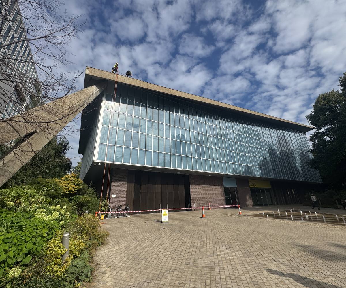
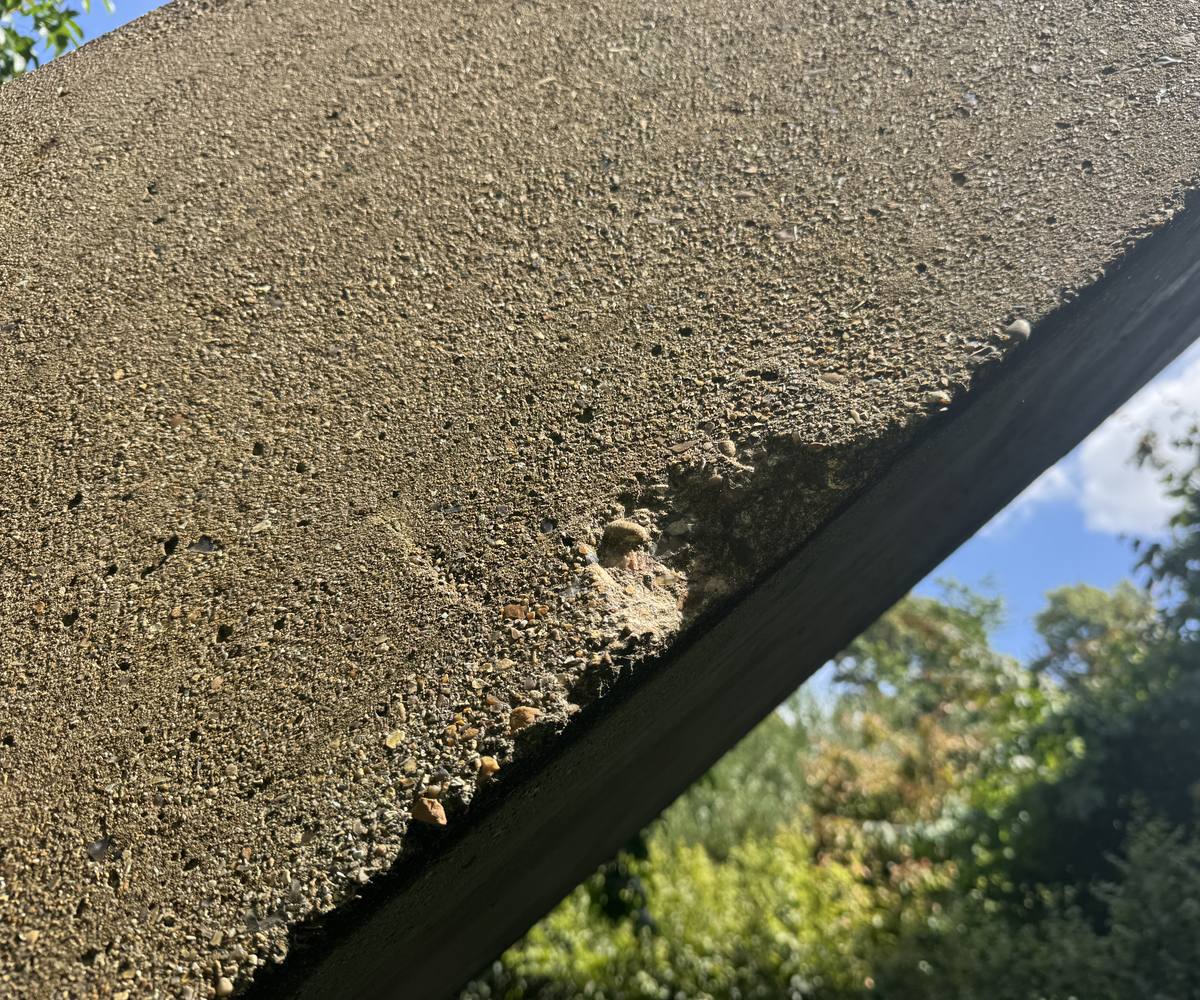
Externally we tested the raking columns and the roof soffits and fascias, working by rope access; internally, the roof trusses, rafters and paraboloid shell. At selected locations we measured the depth of cover to the reinforcement with a covermeter, and measured carbonation depth by spraying phenolphthalein onto freshly broken concrete in accordance with BS EN 14630. Schmidt rebound hammer readings were taken on external and internal elements to give an estimate of the concrete’s compressive strength.
Concrete dust samples were taken from the cover zone and analysed by a UKAS-accredited laboratory for chloride content, to assess the risk of chloride-induced reinforcement corrosion, and for high alumina cement (HAC), which was widely used in UK precast concrete in the 1960s and carries long-term durability concerns. The results informed our interpretive report, which set out short, medium and long-term repair options and a specification for repairs.
Design Museum
The museum’s glazed elevation beneath its concrete roof edge, with an inclined concrete column on the left, two rope access operatives on the roof edge and a taped exclusion zone on the paved forecourt
Design Museum
Rope access operative, seen from below, stepping over the edge of the concrete roof slab above the top of an inclined concrete column, against a blue sky
Design Museum
Interior view up into the roof: a painted concrete shell soffit and converging concrete roof members meeting at a line of rooflights
Design Museum
Close view of a spalled edge on an exposed aggregate concrete column, with trees and sky behind
Faversham Western Link Bridge
Location
Faversham
Date
June 2024
Description
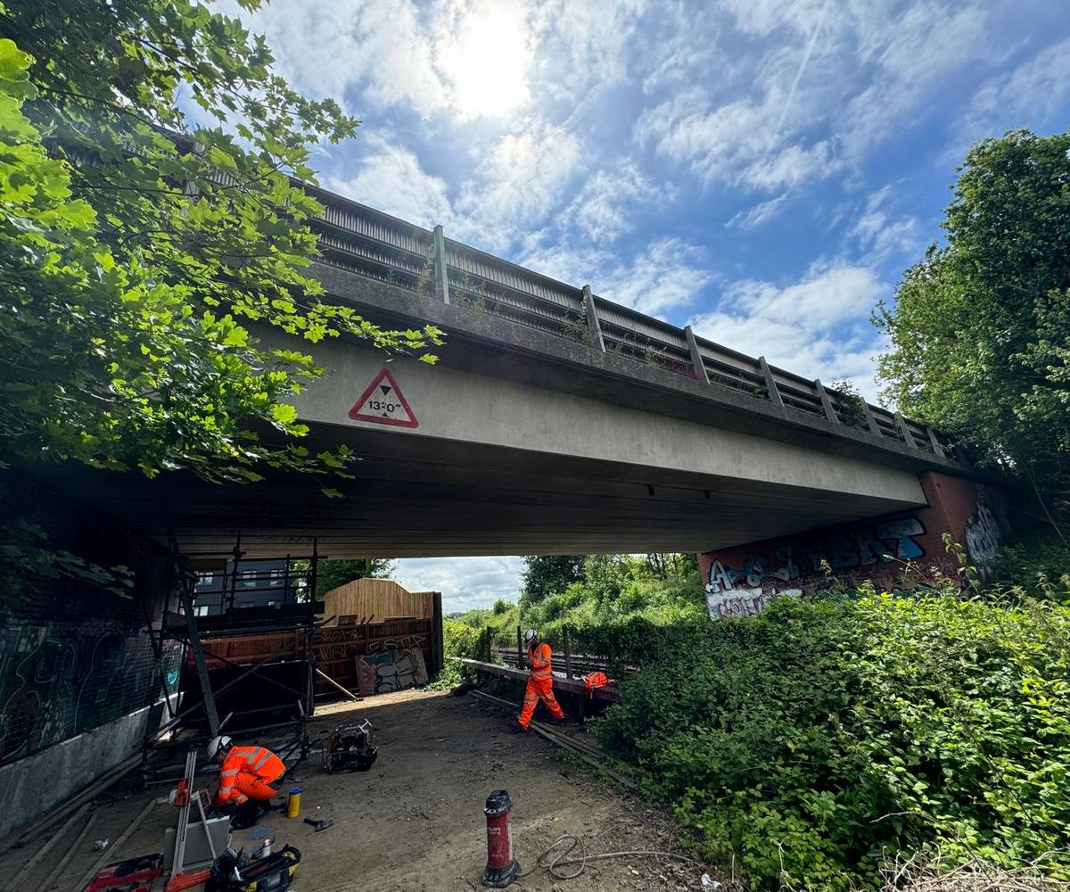
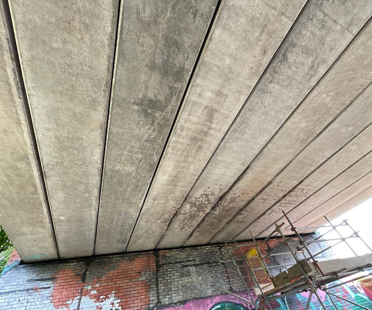
We carried out a concrete condition survey and testing of the Faversham Western Link bridge following a fire. The single-span bridge carries the Western Link Road over the railway line between Faversham and Teynham stations, on precast, prestressed concrete beams supported by masonry abutments.
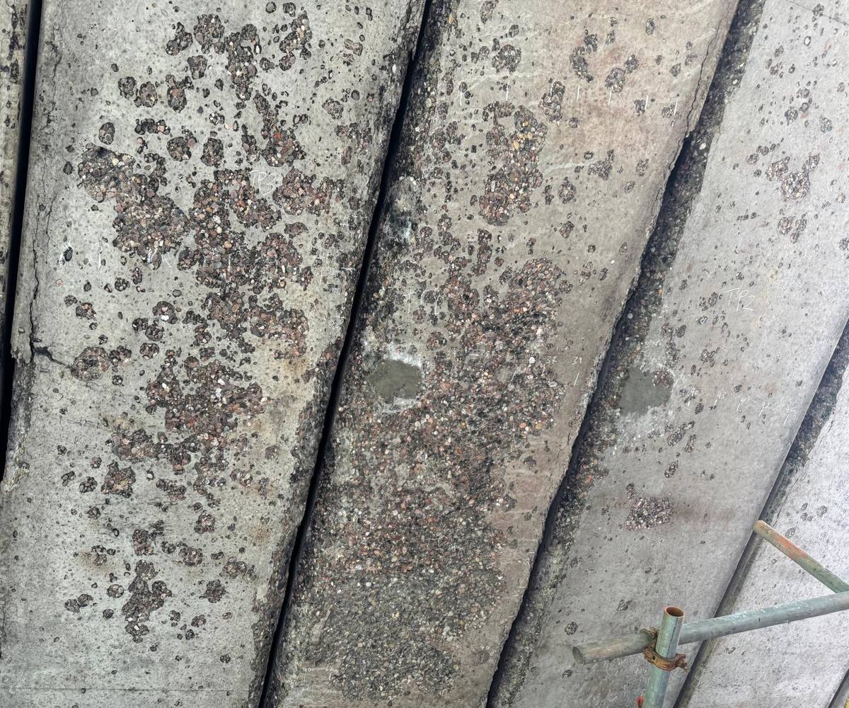
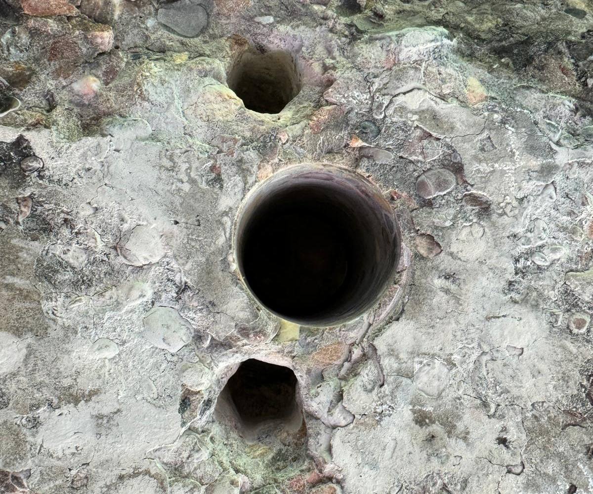
Working from a tower scaffold, we carried out a visual and hammer rap survey of the fire-affected beam soffits and a covermeter survey at five test locations to measure the depth of concrete cover. We took two concrete cores from the beam soffits for petrographic examination in a laboratory, to establish how far heat from the fire had travelled into the beams. The core holes were made good with hand-placed repair mortar.
Our report compared the depth of heat penetration with the cover to the prestressing tendons, to show how much concrete would need to be removed before repair. We recommended removing the damaged concrete by hydrodemolition, so as not to damage the tendons, and reinstating the soffits with a spray-applied repair material.
Faversham Western Link Bridge
Side view of a concrete road bridge spanning a railway cutting, with scaffolding and two workers in orange high-visibility clothing beneath it and drilling equipment on the ground
Faversham Western Link Bridge
Underside of the bridge deck showing parallel precast concrete beams resting on a brick abutment, with darkened and patchy areas on the beam soffits and a scaffold tower to the right
Faversham Western Link Bridge
Close view of the beam soffits with widespread patches of exposed aggregate, chalk-marked test locations TP2 and TP3 and two small grey patches, with a scaffold tube at the bottom right
Faversham Western Link Bridge
Close-up of a cleanly cut circular hole in a concrete surface with rounded aggregate exposed around it, and two smaller irregular holes above and below
Heathrow Data Centre
Location
Hounslow, London
Date
July 2024
Description
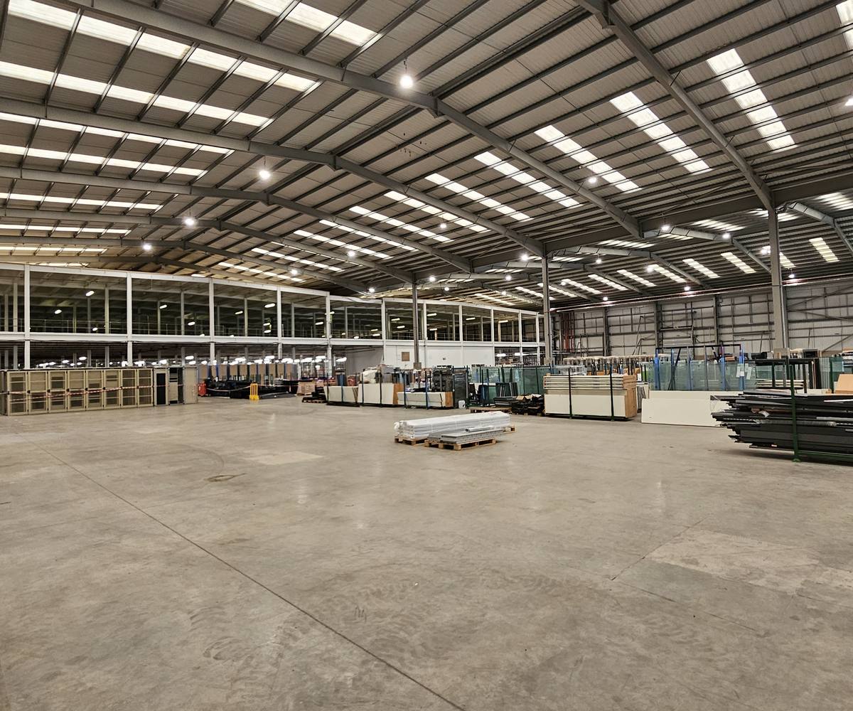
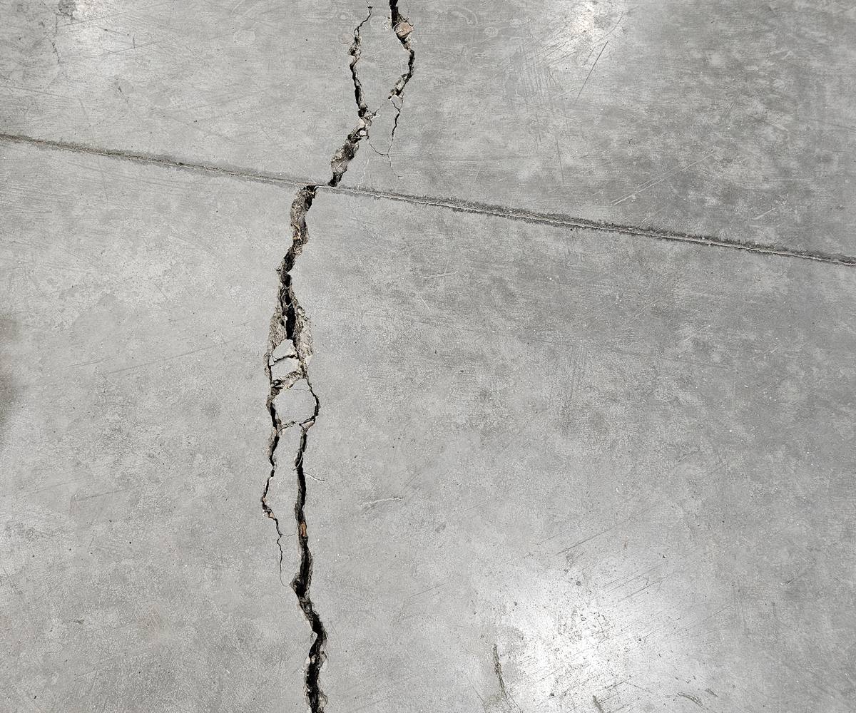
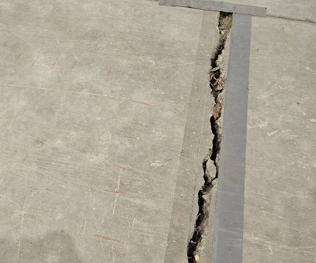
We carried out structural investigations and materials testing on the fibre reinforced, ground bearing concrete floor slab of Heathrow Data Centre, working to a specification issued for the project. The slab showed widespread cracking, and the brief was to find how deep the cracks ran and to confirm the as-built construction.
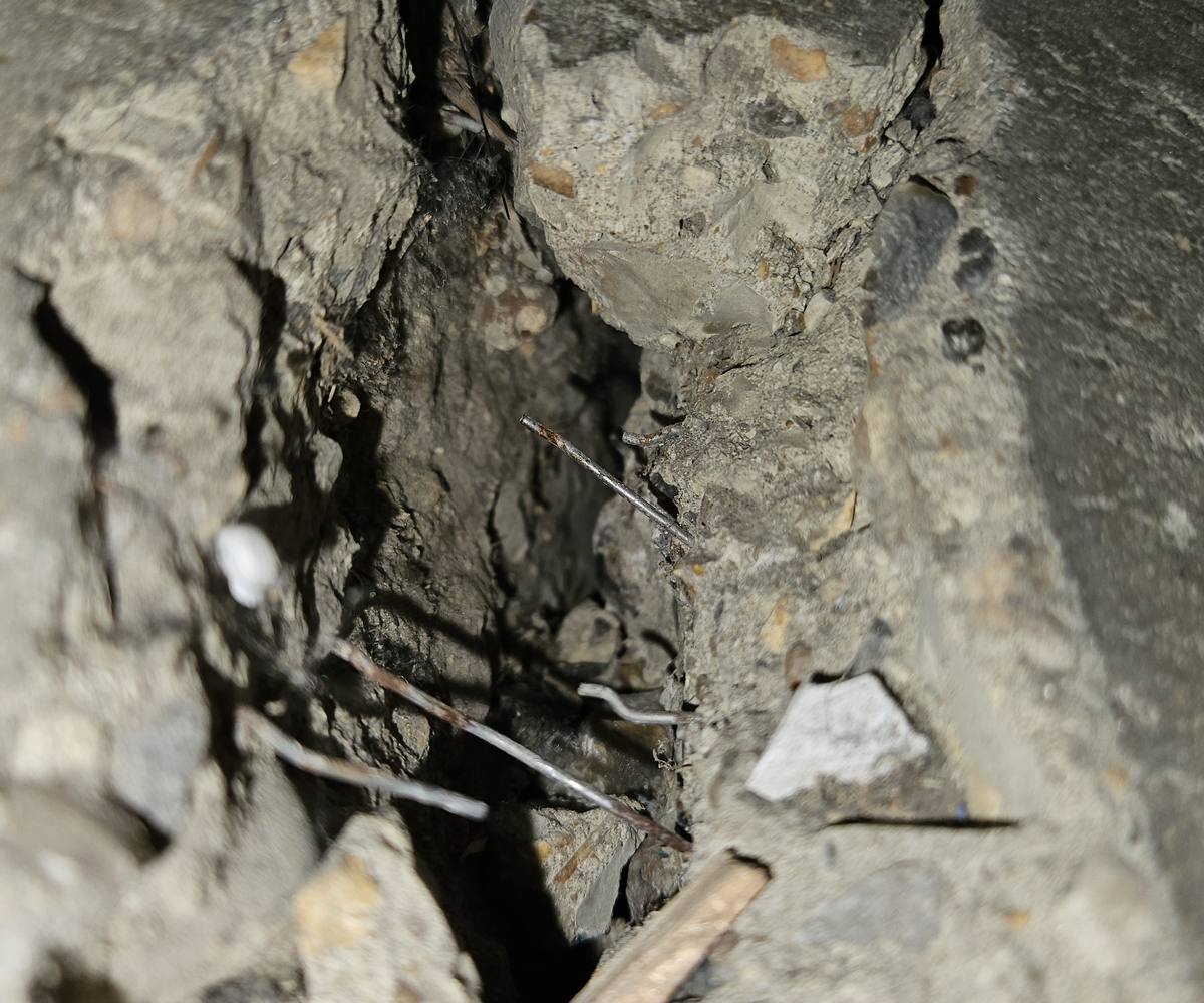
Steel fibres in the concrete interrupted the ground penetrating radar signal, and ultrasonic testing could confirm the slab thickness but not locate the reinforcement, so we used stitch coring instead, cutting cores through the full depth of the slab over cracks and joints to reveal its make-up and the sub-grade beneath. At selected locations we over-cored and broke out the concrete to expose the embedded reinforcement and log its size, type and condition, and we fixed Demec studs across cracks at three locations for crack monitoring.
Two cores were tested for compressive strength, two reinforcing bar samples went for tensile, hardness and metallographic testing and chemical analysis, and a concrete sample was examined petrographically, including its cement content and the volume of steel fibres. The compressive, tensile and petrographic testing was carried out by UKAS-accredited laboratories, and every slab opening was reinstated with a high strength concrete repair material.
Heathrow Data Centre
Wide view across a large concrete-floored hall under a steel portal frame roof, with a white steel mezzanine and stacked materials at the far side
Heathrow Data Centre
Wide, irregular crack running across a concrete floor slab and through a straight joint line, with broken edges along its length
Heathrow Data Centre
Close view into an open crack in a concrete slab, with thin wire fibres protruding from the broken concrete
Heathrow Data Centre
Open crack in a concrete floor running alongside a grey metal joint strip, with red marks drawn on the slab surface beside it
Heaton Park Telecommunications Tower
Location
Manchester
Date
November 2024
Description
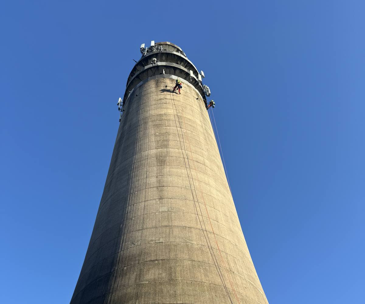
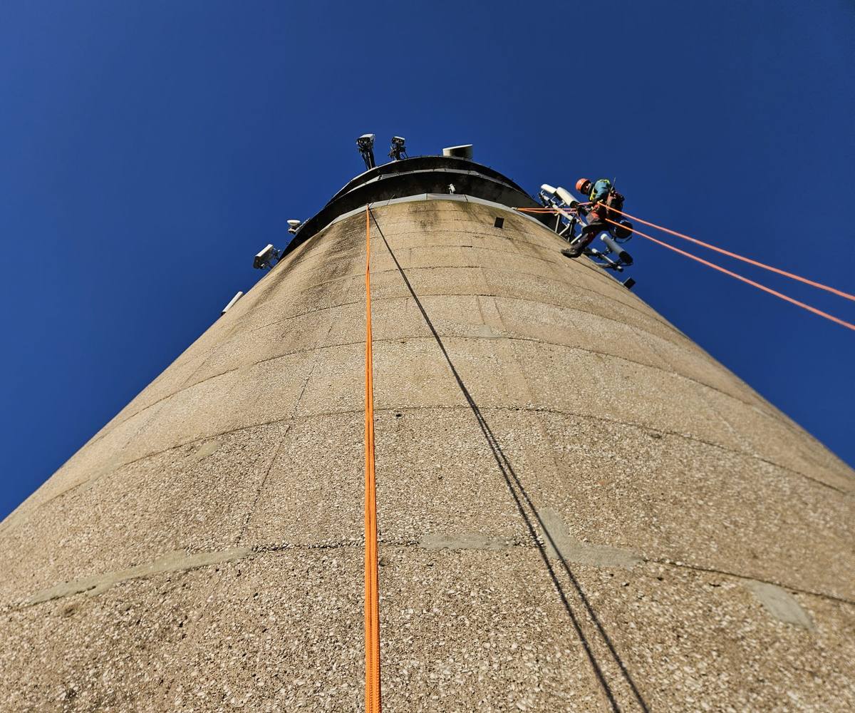
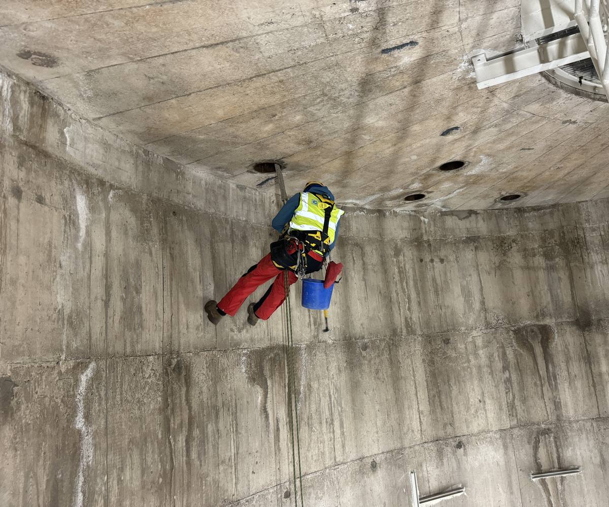
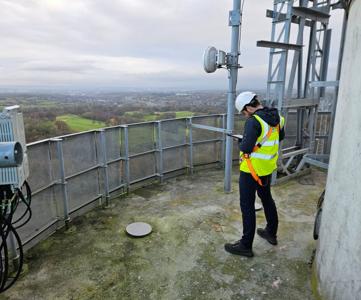
We carried out an external and internal concrete condition survey of the Heaton Park tower, a 60.5 m reinforced concrete telecommunications tower with cantilevered galleries at its upper levels. Alongside a visual and hammer rap survey, we tested the concrete at 20 selected locations, reaching the external faces by rope access.
At each location we measured the depth of cover to the reinforcement with an electromagnetic covermeter, in accordance with BS 1881: Part 204, and the depth of carbonation by spraying phenolphthalein onto freshly broken concrete, in accordance with BS EN 14630:2006. Carbonation removes the alkaline protection the concrete gives the steel, so the cover readings let us judge the carbonation depths against the position of the reinforcement.
We also drilled concrete dust samples from the 5–30 mm zone of cover, discarding the first 5 mm to avoid surface contamination, and had them analysed for chloride content by a UKAS-accredited laboratory in accordance with BS 1881: Part 124. Chloride content is crucial to choosing the correct repair specification, and the results informed our report, repair recommendations and bill of quantities for the client.
Heaton Park Telecommunications Tower
Looking up the tapering concrete shaft of the tower from ground level against a clear blue sky, with two rope access operatives on ropes just below the galleries at the top
Heaton Park Telecommunications Tower
Looking up the concrete shaft of the tower, with an orange rope running down its face and a rope access operative in a helmet and harness near the top against a blue sky
Heaton Park Telecommunications Tower
Rope access operative in a harness, seen from behind, suspended against the inside wall of the tower beneath a concrete soffit, with a bucket and hammer hanging below
Heaton Park Telecommunications Tower
Surveyor in a hard hat, hi-vis vest and harness recording on a tablet on a gallery deck of the tower, with steel railings, antenna equipment and open countryside beyond
Soft Drinks Factory
Location
Sidcup
Date
March 2025
Description
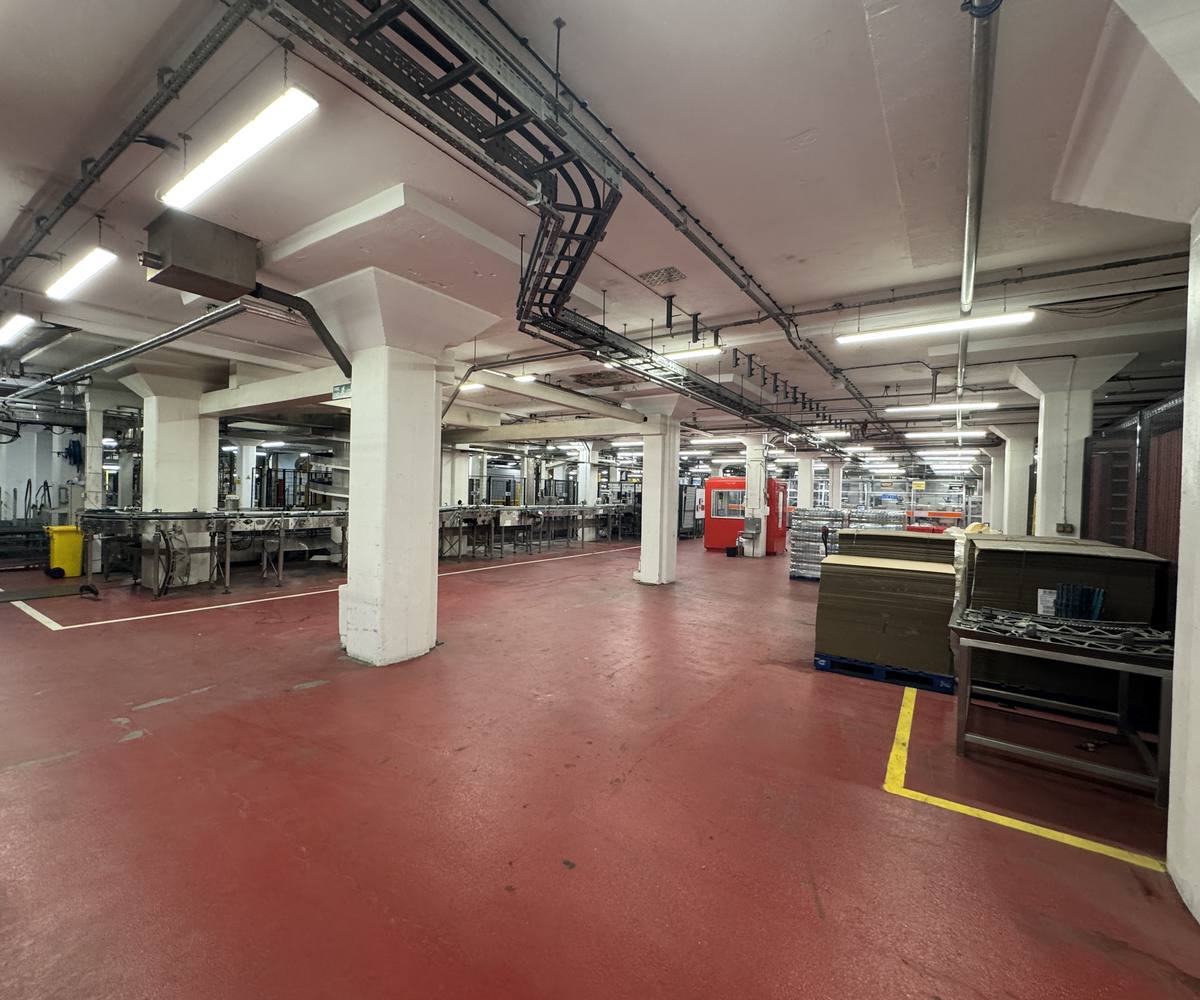
We carried out a concrete condition survey and testing at a soft drinks factory in Sidcup. It covered the soffit and beams of the palletiser area, where the reinforced concrete frame has column capitals and drop panels, and the slab, soffit and beams of the production floor above Line 1.
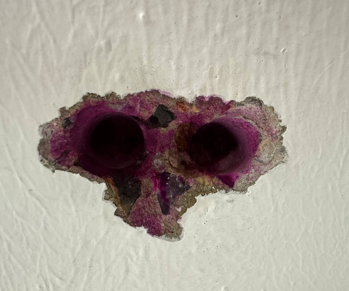
Alongside a visual and hammer tap survey, we took covermeter readings and measured carbonation depth at selected locations in each area, the latter by spraying phenolphthalein on freshly broken concrete, to BS EN 14630:2006. Read together, the two show whether carbonation has reached the reinforcement and removed the protection the concrete gives it.
Concrete dust samples from each area were analysed for chloride and sulphate content by a UKAS-accredited laboratory. The results informed our recommendations, repair specification and bill of quantities.
Soft Drinks Factory
Wide view of a factory floor with white-painted concrete columns with flared heads supporting a concrete soffit, cable trays and lighting overhead and a red painted floor
Soft Drinks Factory
Small breakout in a painted concrete surface with two drilled holes, the exposed concrete coloured bright magenta
Soft Drinks Factory
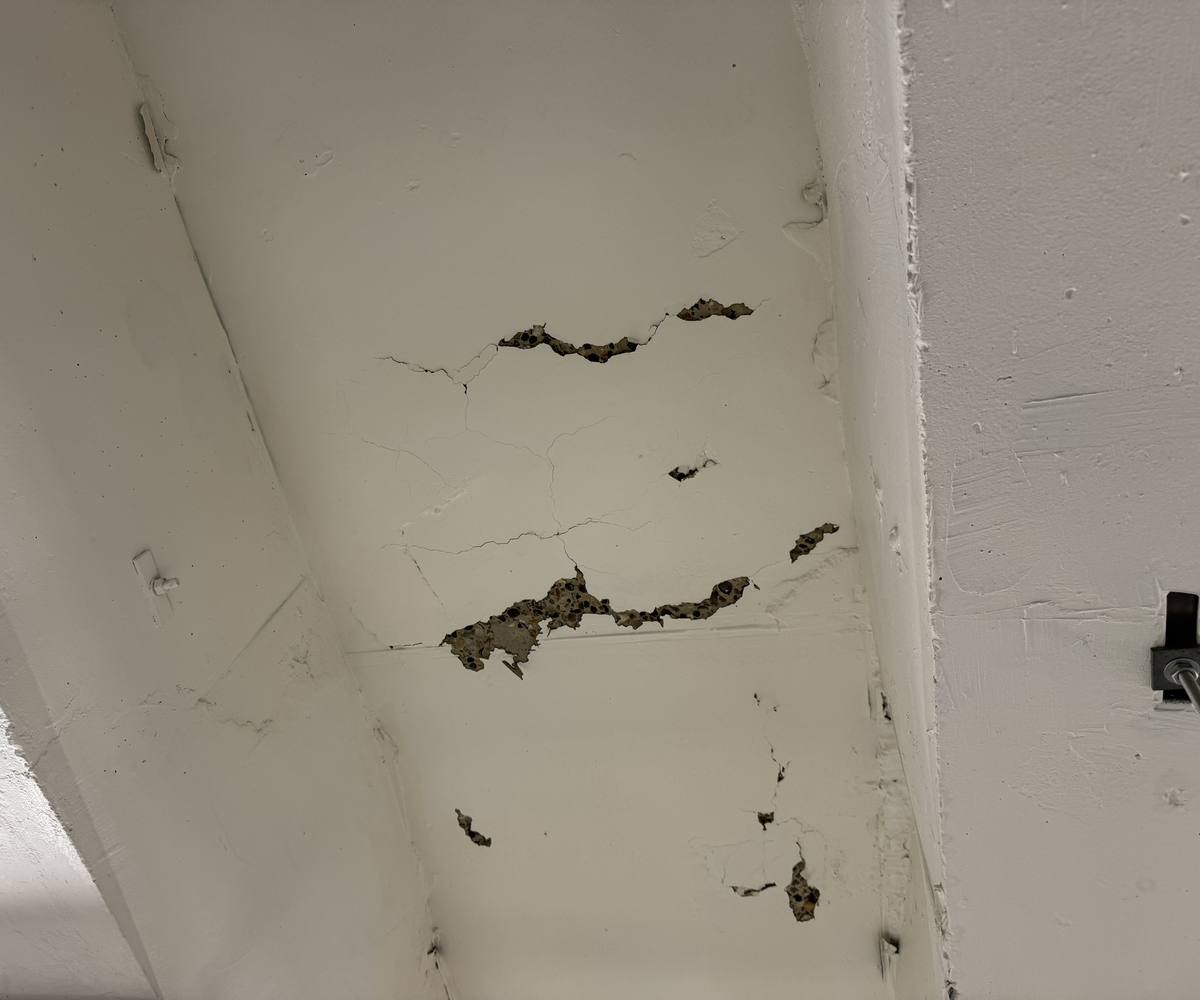
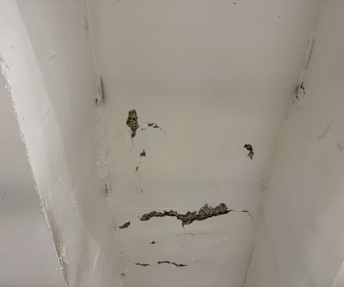
Painted soffit between two downstand beams, with a network of fine cracks and several spalled patches where the paint and surface have come away to show the aggregate beneath
Soft Drinks Factory
Painted concrete soffit between two downstand beams with fine cracking and small spalls exposing the aggregate
Talk to us today
See how we can help, with a no-obligation initial discussion.
We track how people interact with our online web content and resources, and some of that tracking involves storing cookies on your device. By continuing to use our site you accept that you agree to this. For more details see our Privacy Statement.